Posts

Showing posts with the label DCC

DCC Decoder v3 Firmware

Well I have been working on my arduino based DCC Decoded and am proud to announce that I have been able to create a firmware update Link Removed . This enable a couple of features on my pcb's which have had slight rewiring due to my silly errors. I still need to correct a few errors (such as a recently occurring servo chatter) but most seems to work fine. New Features include push button programming (in a similar fashion to train tech signal where you press a button and it takes the next address thats pressed) LED to show when in programming mode EEprom utilization to remember address when powered off Changes to come Push button adjustment of servo movement limit (may require new PCB version or control board) PCB Changes Added Reference ground Changed pushbutton resistor connection Removed 3 unusable pin headers Corrected resistors outlays for 1/4w resistors Added GND and 5v layers If anyone would like a copy of my new pcb and the updated list of components requi...
Starting from scratch

Image
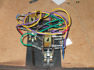
No, don't read too much into that title, it just means track laying is complete though ballasting is still needed on the yard tracks. It actually links to the fact that I am now starting to slowly add buildings, the first being a scratchbuilt building to cover up some point motors. The 'Rats Nest' to cover up. So I have made a template building out of plasticard ( .30 thou from work  though any will probably do). This so far is roofless and has a slot in the wall facing the tract to allow the point rodding to go through. The basic plasticard template Now as I said, this is just a temporary mock up, the final will be made either from slaters, south eastern finecast or wills stone sheeting, now as can be seen already, even without a roof it looks much better, so imagine what the final result may look like, and then tell me as I still haven't fully decided what the building will be, though a water tower is likely at this point in time. But now I have s...

Dcc decoder v2 shield

Image
Although I haven't updated much for a while, I have been working on things in the backround such as a printed shield for the dcc decoder scriot i am writing for the arduino. So far I am on my second prototype but it will be the first with any components, mainly as the original was missing a route. Now the good thing is that you do not have to use it with dcc, but can use it with pushbuttons (omit some components and change a few linea of code.) The first picture is of the original prototype. PCB,  this one although could be used missed a connection to jp9 which meant that I would only be able to attach 10 instead of 11 servos to it. The second picture shows the updated version, this has been fixed so all 11 servos can be attached and used. It also, as you may have noticed, got a few more component holes on it, this is to facilitate a learn button for reprogramming, as well as to incorporate the required components to reduce a 12v supply to a 5v supply. All the componen...

Building a DCC Decoder

Image
For some time I've been considering various ways of controlling points, the one thing that keeps coming back to me is to operate them through DCC, but perhaps also link it to a control panel that will allow me to combine it with the toggle Switch method. For some time I've been looking at Arduinos  and they may do what I need them to do. So far I've got a basic circuit and code set up, all thats needed is a servo to Test, which is on order, I shall perhaps upload a video once its all working. Though I'm sure some people may like to see whats been done so far. The Circut for the monitor which allows the Arduino to see whats going on Myna Bay DCC Monitor An Arduino Uno, any Arduino can be used for this, though its easier if you can attach shields to it The Prototype shield set up with the DCC Monitor Circuit  Now although Myna bay Provides a DCC monitor code to load onto the Arduino, it doesn't help us much as it only provides binary feedback...

Route Indicator Circuit

Image
So for some time I've been trying to come up with a simple way of indicating what direction a point is set too without too much trouble, fortunately I cam across  this post  on rmweb regarding using bi-color leds with electrofrog points. Now the idea stayed floating in my head for some time, given that I had tried it with individual leds first but it wasn't quite something I was happy with. Though as mentioned as I came across the post I decided to give it a go so I got all the items I needed from maplins. Those being a breadboard, leds (bi-color type) resistors, tripad board, the diodes I already had from another project. How the circuit appears on a breadboard Then The process begins of putting it on a tripad board (like stripboard but each each track is separated into 3 holes) Copper Track Side of circuit board Component Side of circuit board. Now you may have noticed there's no led on the finished board...

Running back and Forth

Image
Quick update first regarding my last post. The problem regarding the track constantly needing cleaning is solved (amazing how a plug not fully connected can affect the running of a layout). So onto the main subject of the post. I have got myself an Autocoach and B set Coach to run behind my 14XX, a few things are needed to be done. First step in a lot of coach rebuilds/repairs is to completely disassemble said coach. Autocoach Fully Disassembled,  front shows both bogies and broken under frame detailing. Middle shows base and weight for coach. Back is clearly the coach and roof is removed and loosely placed back on top First things I plan to do is re-wheel the bogies with metal wheels (which is why they are currently missing), repair the broken part of the under-frame. I will also look at weathering the under-frame and the bottom of the coach. Finally I will add detail to the inner of the coach, added painted seats and passengers. Once fini...

Need More Power

Image
Since my last post, I've fitted a DCC chip to the 14xx (quite simple and apologies for not adding pictures). However as it's my shortest loco I've found it having issues going over the pointwork on the inner track, such as stalling when on the point blades between the main rails and the electro frogs, after a bit of testing and installing extra wire at the toes of the points I've found that what is causing the problem. It would seem that for some reason the point blades on the inner loop isn't picking up power off the main rails as they do on the outer loop, to bypass this I'll add extra droppers into the point as shown in the image below.  In the image the red rails are fed from the red wire of the dcc bus and the black from the black wire of the dcc bus, the blue section is fed from the point motor to switch the polarity depending on the position of the blades. The additional wires to add extra power to the points will be added where the small circles ...

New Addition to the fleet

As my railway is going to run what I feel like running on it, I have decided recently to buy the new Hornby GWR 14xx, now of course this, because it is using old airfix tooling, has no socket for a decoder, so in order to make it work with my control system, I need to install a decoder. Thankfully hard-wiring decoders into steam engines is a little easier then fitting them to diesel as there are no light to wire in, instead all I will need to do is to de-solder the wires from the pick-ups to the motor as well as removing the capacitor (as this is not needed with dcc), and then solder the red and black pick up wires to the red and black wires on the decoder and also solder the orange and grey (correct me if i'm wrong on this) wires from the decoder into the motor. When I do this, I'll update once more on my progress.

Modifying a 56

So, I've decided to make a few modifications to my class 56. To begin with, to smooth out its running I'll simply be chopping off the capacitor near the motor, as from my understanding, this can cause problems when running a loco on dcc. Once this is done, and I've made any other requirements for it to run smoothly, I will work on motorizing the roof fans. From what I've read, this can be done by installing an additional decoder (and set it to a different number) which connects up to a specific motor (a mashima 1020) which should fit in the space left when removing the drive shaft. Then all I should need to do is to program the chip before installing it (I'll be making use of the speed function that usually controls the loco's main motor) and add a little rubber ring to the end of the motors drive shaft to enable it to rotate the fans at the speed I require, when I want it. When I start on this, I will add pictures showing what I'm doing.

Wait ages for one and two come along at once.

Image
As not much has been done to the layout recently, the blog laid more or less dormant. Though now of course two posts come up at once. So recently my birthday came around and I gained a few extra wagons, now I already had the appropriate loco to pull them so I just had to chip it. This however is where the problems started, once I installed the chip and reassembled the body, I noticed a strange issue with the lighting, only one ends lights, if any were on when they were meant to be on. So a bit of fiddling later, almost giving up and returning it and checking the internet, I came across a couple of articles about the lights on Hornbys class 56. Satisfied that it wasn't a dodgy unit, to a certain extent, and more of a manufacturing fault, I reinstalled the chip (having removed it earlier to test it on analogue control before almost giving up completely). After cleaning the light contacts and making adjustments to the springs on the body to help improve the lighting powe...

Setting Track for Dcc

Image
So I keep telling myself that I'm not going to be using settrack on my layout due to the issues it causes if anything with a short wheelbase is run over it (mainly shunters with 0-6-0 or 0-4-0 wheel arrangements) But as happens I see that I can add more track to part of the layout and this track, due to the geometry, has to be set track, so I set about making it live, but of course I refuse to use Hornby's DCC staples, so I set about making my own modifications.   The back of  a Peco settrack point, as out the box   Most of the webbing cut away along one section.   Small sections of wire soldered to join the required rails   View from top once installed on track.  Now although they may be slightly more intrusive at this point, they should more or less disappear when the track is ballasted.

Complete and utter frustration

Image
Now this is what you call frustration, I purchased 1 roll of woodland scenics track bed, purely because from looking at the length I thought it would be enough, clearly though, it wasn't enough, leaving me with gaps under the left side curve. Fortunately though I got all the other track bed down without too much of a problem. So my next step is to get another pack of track bed, which I will need for the yards anyway so most of is should get used up. Then I'll wire in the power to the bus lead under the board to send a test train round on, this will pick up on any possible problems I may encounter before I take up all the track, go over it all with a track rubber and stick it down. I'll then test it all again to be sure everything is fine before installing the point motors which will be controlled via dcc, I know some people don't like the idea of dcc points but I have no room for a control box and sometimes I'd like to sit down and watch trains go round, c...

Laying the basics

Image
So this is how it looks for now, of course nothing is actually fixed in place as most of it will be risen up (thought I'm not sure how some of my locos will manage the inclines so I guess I'll have to see when it comes to it. Now on the left side I'll be using some wood to rise up the track to the required hight, but of course to have motors under the track I'll need to leave gaps in the wood as well as putting a thin sheet over the top to conceal the gap. Despite this I have been temped to use some of the woodland scenics inclines and risers to do the same thing, my only issue with the wood at the moment is that they are not wide enough to fully conceal the under board motors though I can remedy this when it comes to adding the scenery. Initially I was going to make the passing loop removable in one section, though I now believe that that will make things more difficult for me and perhaps my better option would be to forgo that idea. Instead I'm tempted to...

Making it Modular

Image
Not quite sure how I will manage this, but my plan is to make it as modular as I can, mainly so if I ever get extra room for it I can just add extra boards in between the existing ones. So my first thought is to make areas of track simple to remove, now I've seen this done with scenery which is easy enough, but with track that includes a bundle of points is going to be tricky and at the moment I'm not sure how I'm going to overcome this purely because of the wiring needed and my concern is where is this heap of wiring going to go and how am I going to make it easy to connect up without going through dozens of wires and connecting them appropriately. I am sure there are ways of doing this without creating obtrusive wires and maybe my decision to use dcc for points as well could help. Now as you may be able to tell, the coloured bits of the plan need to be easily removed, although it requires a little testing, one thought is to scratch build a building, maybe a signal...