Posts

Showing posts from 2013

Starting from scratch
Image
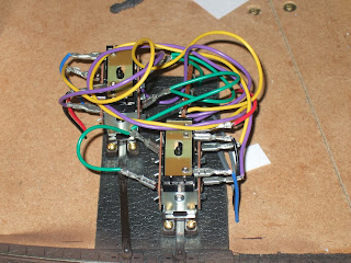
No, don't read too much into that title, it just means track laying is complete though ballasting is still needed on the yard tracks. It actually links to the fact that I am now starting to slowly add buildings, the first being a scratchbuilt building to cover up some point motors. The 'Rats Nest' to cover up. So I have made a template building out of plasticard ( .30 thou from work  though any will probably do). This so far is roofless and has a slot in the wall facing the tract to allow the point rodding to go through. The basic plasticard template Now as I said, this is just a temporary mock up, the final will be made either from slaters, south eastern finecast or wills stone sheeting, now as can be seen already, even without a roof it looks much better, so imagine what the final result may look like, and then tell me as I still haven't fully decided what the building will be, though a water tower is likely at this point in time. But now I have s

The final name change

Well after some thinking and consideration, I have decided the final name for my layout will be Hellier Train Care. It will be a small train care facility that can act as a service point for locomotives of all types (bar electric, as currently there are no electrified lines in the south west) It will remain based between Taunton and Yeovil and will be able to, for now only fuel up diesels, but its shop will be able to handle steam locos to do minor service between specials, I may also have it as stabling point for a heritage loco (that may or may not have been preserved in real life). I would also like it to have a turntable, but I believe that at the moment with size constraints it's unlikely, however when it (I) gets a larger home and the layout is expanded. At that point I will most likely be able to add more onto it and hopefully the train care facility will make up only a small fraction.

The Price of decoder parts

Well, the decoder is almost complete (trying to find the right headers to connect the servo to the board), and so far I have found out how much all this would cost me, knowing what I know now, and this is just for parts. Below is a list of parts plus the prices Product Code Quantity Product Description Unit Price Discounts Line Total 22-0822 11 3 Way 2.54mm Kk Molex Housing £0.13 £0.00 £1.40 58-0598 1 6n137 Highspeed Logic Gate Optocoupler £0.79 £0.00 £0.79 64-0098 1 10k Cr12 0.125w Cf Resistor - Pack of 100 £0.69 £0.00 £0.69 47-3416 5 1n4148 Signal Diode 75v 150ma (tru) £0.01 £0.00 £0.05 85-3077 1 12vdc 2.5 AMP International Plug Top Psu £15.92 £0.00 £15.92 20-0960 1 Switchcraff DC Power Socket PCB Mount 2.1mm £0.65 £0.00 £0.65 08-0919 2 1uf 2.5mm Y5v Dielect Ceramic Capacitor £0.11 £0.00

Dcc decoder v2 shield

Image
Although I haven't updated much for a while, I have been working on things in the backround such as a printed shield for the dcc decoder scriot i am writing for the arduino. So far I am on my second prototype but it will be the first with any components, mainly as the original was missing a route. Now the good thing is that you do not have to use it with dcc, but can use it with pushbuttons (omit some components and change a few linea of code.) The first picture is of the original prototype. PCB,  this one although could be used missed a connection to jp9 which meant that I would only be able to attach 10 instead of 11 servos to it. The second picture shows the updated version, this has been fixed so all 11 servos can be attached and used. It also, as you may have noticed, got a few more component holes on it, this is to facilitate a learn button for reprogramming, as well as to incorporate the required components to reduce a 12v supply to a 5v supply. All the componen

Big Update

Image
Been awhile since my last update, so pardon me if this one is a bit long. First off the class 20 conversion is well underway, the original loco has been stripped and had new fuel tanks, lights and mu sockets fitted External Fuel tanks mk1, I have slightly redone them since the above picture was taken for a better fit. Bath time! Class 20 goes for a dip in Precision Paints paint stripper Stripped loco with test fit fuel tanks Fuel tanks glued on sporting mainly trains rivet strip along the bottom Wipac Lights fitted on both ends along with MU (multiple unit) sockets I have also added to my tunnel by spraying the ends grey (mixture of railmatch rail grey and humbrol dirty black) before adding smoke marks where locomotives would pass under. (Not pictured but will add later) I have also started the process of adding people to my pullman coaches (mainly by taking two apart). The figures will be purchased in the next few weeks. Devon Belle Observation Car

Building a DCC Decoder

Image
For some time I've been considering various ways of controlling points, the one thing that keeps coming back to me is to operate them through DCC, but perhaps also link it to a control panel that will allow me to combine it with the toggle Switch method. For some time I've been looking at Arduinos  and they may do what I need them to do. So far I've got a basic circuit and code set up, all thats needed is a servo to Test, which is on order, I shall perhaps upload a video once its all working. Though I'm sure some people may like to see whats been done so far. The Circut for the monitor which allows the Arduino to see whats going on Myna Bay DCC Monitor An Arduino Uno, any Arduino can be used for this, though its easier if you can attach shields to it The Prototype shield set up with the DCC Monitor Circuit  Now although Myna bay Provides a DCC monitor code to load onto the Arduino, it doesn't help us much as it only provides binary feedback

Route Indicator Update

Image
Though I havn't actually installed them yet I thought it may be worth doing a little update on my route indicator circuits since last time I photographed it, it has been slimmed down and it has also been suggested to me to upload a copy of the circuit diagram, so here goes. Circuit Diagram from RMweb for point indicator diagram using frog polarity Track side of Tripad Board Component side of Tripad board The main difference between these and my early prototype is that I've slimmed it down into 3 rows instead of 4 and the wires are now fed through the holes in the board to be soldered on the copper clad side. On all of the boards I made up, I also got into the habit of using a digital multimeter to ensure that power flowed through each part of the circuit as it should. I am at this point considering buying the required components to make more and perhaps sell them as well, but this depends if anyone would be interested in buying them.

Route Indicator Circuit

Image
So for some time I've been trying to come up with a simple way of indicating what direction a point is set too without too much trouble, fortunately I cam across  this post  on rmweb regarding using bi-color leds with electrofrog points. Now the idea stayed floating in my head for some time, given that I had tried it with individual leds first but it wasn't quite something I was happy with. Though as mentioned as I came across the post I decided to give it a go so I got all the items I needed from maplins. Those being a breadboard, leds (bi-color type) resistors, tripad board, the diodes I already had from another project. How the circuit appears on a breadboard Then The process begins of putting it on a tripad board (like stripboard but each each track is separated into 3 holes) Copper Track Side of circuit board Component Side of circuit board. Now you may have noticed there's no led on the finished board, thats what the orange and gray wires are for

The Fleet so Far

Image
For some time I have been hunting for a decently priced display cabinet for my locomotives to be displayed in. Some luck came when I came across one for £29.99 in Lidls, and that is the one shown above, and for the price, it is quite sturdy and well constructed and as such is good for displaying my fleet of locomotives which are as following (from top to bottom and left to right) Hornby Taunton Castle from Date with The Duchy Set Bachmann Class 20 BR Green Sound Heljan Class 33 EWS Hornby Class 142 Pacer Great Western Hornby 1400 (number 4819) GWR Bachmann Tornado Bachmann Class 170 in SWT Bachmann Class 24 br Green Sound and finally Hornby Class 56 in EWS. They all get used and unless they are a multiple unit (IE Class 142 and 170) usually end up being run with a specific set of coaches or wagons, though it is not uncommon to have one set of wagons or coaches for 2 or 3 locomotives, that is untill I procure some rolling stock for the specific locomotive. One other thin